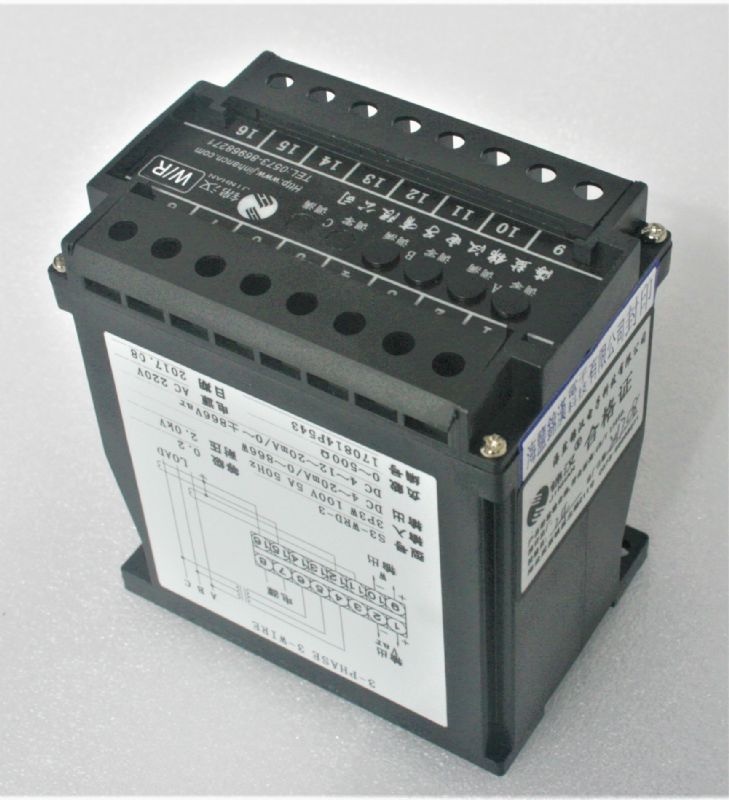
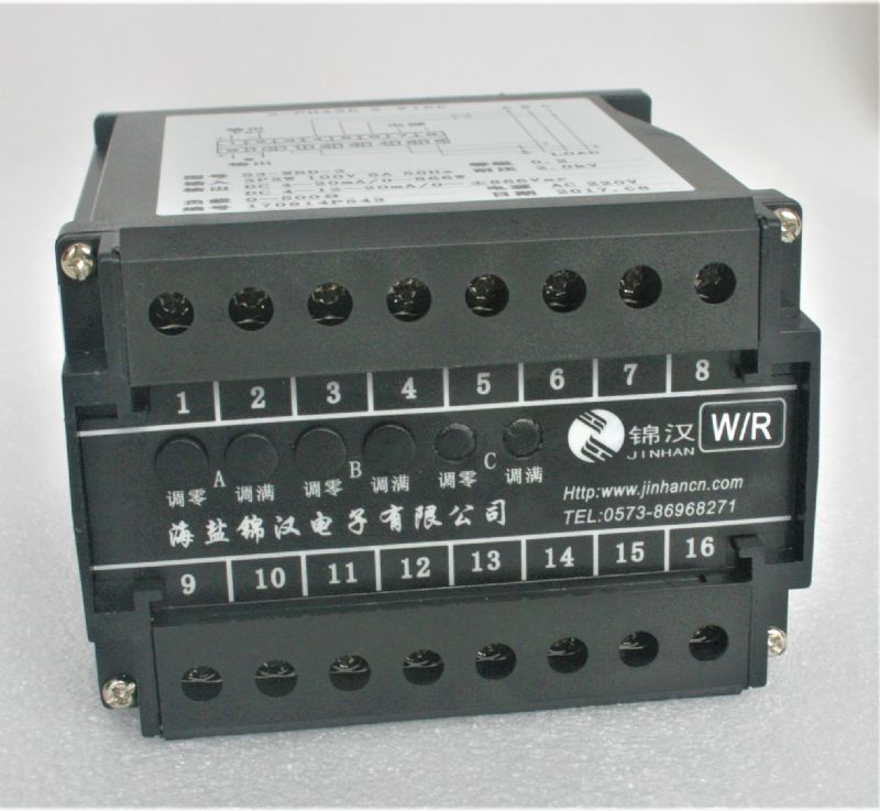
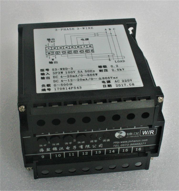
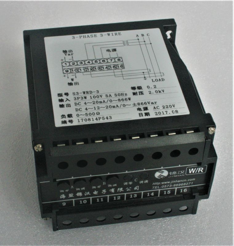
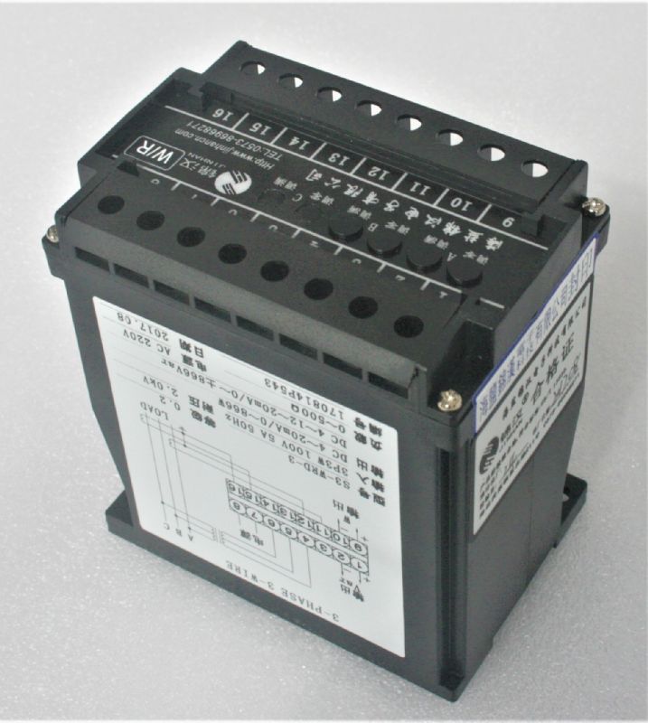
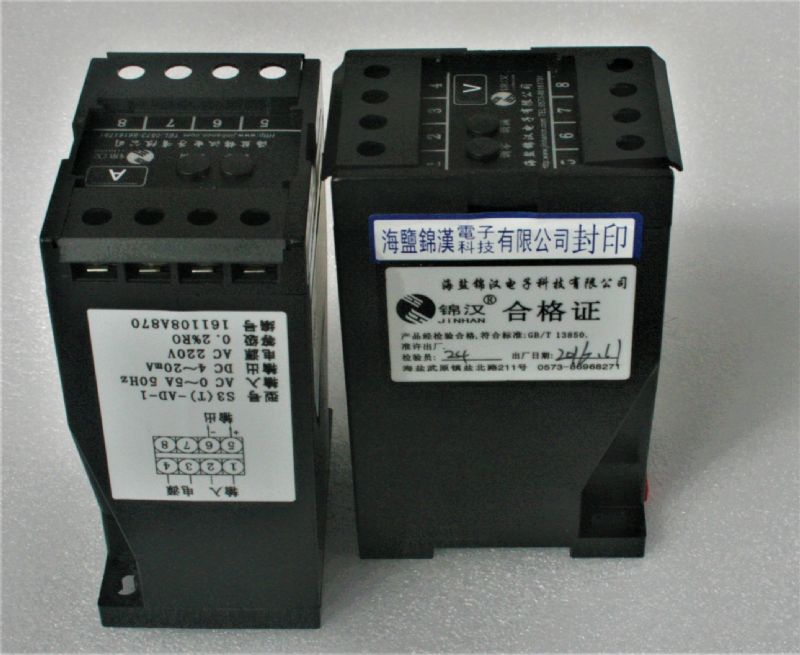
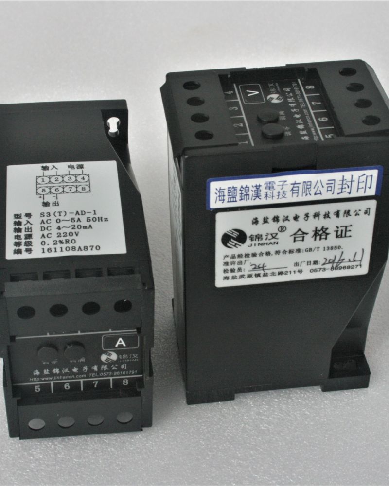
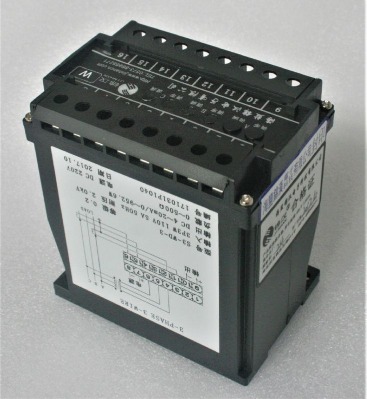
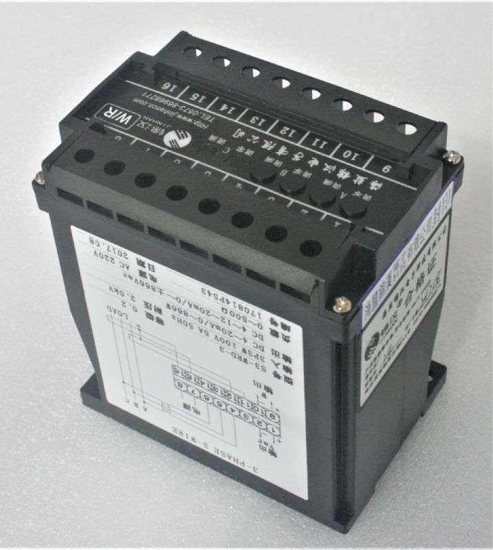
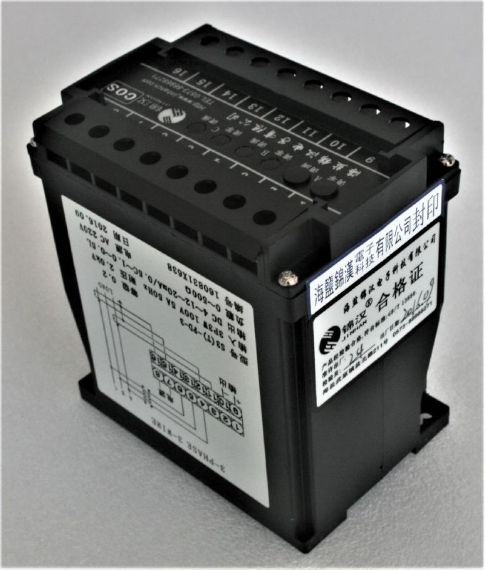
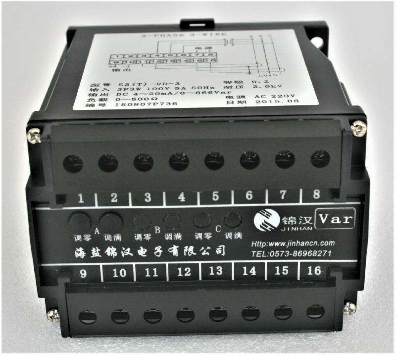
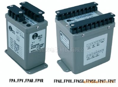
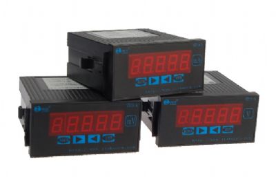
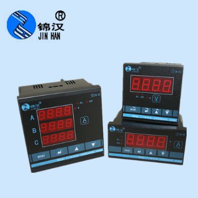
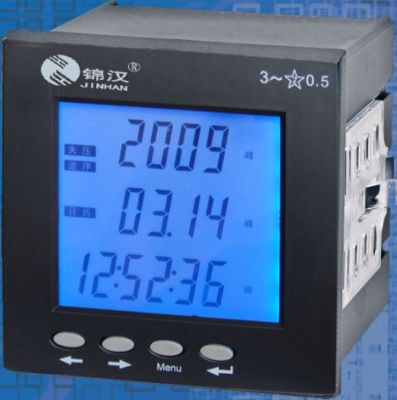
S3-WRAD watt/var/current combination transducer
Quick Overview
S3-WRAD 3φ3W, Accuracy:± 0.2% RO. S3-WAD 3φ3W, Accuracy:± 0.2% RO. S3-RAD 3φ3W, Accuracy:± 0.2% RO. N3-WRAD 3φ3W, Accuracy:± 0.5% RO. N3-WAD 3φ3W, Accuracy:± 0.5% RO. N3-RAD 3φ3W, Accuracy:± 0.5% RO
Related Products
◆Excellent long term stability (4 ~ 20mA, 500 W )
◆Precision measurement even for unbalance system
◆Precision measurement even for distorted wave
◆ High impulse & surge protection (5KV)
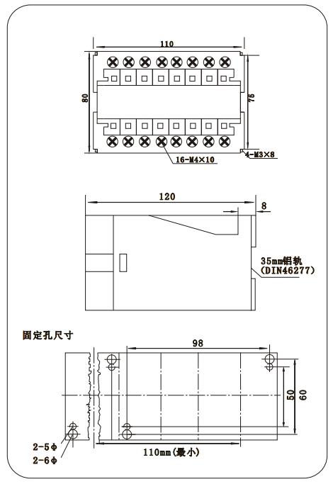
◆The case can be mounted on a 35mm rail which complies with DIN 46277
2.2 Model:
S3-WRAD 3φ3W, Accuracy:± 0.2% RO.
S3-WAD 3φ3W, Accuracy:± 0.2% RO.
S3-RAD 3φ3W, Accuracy:± 0.2% RO.
N3-WRAD 3φ3W, Accuracy:± 0.5% RO.
N3-WAD 3φ3W, Accuracy:± 0.5% RO.
N3-RAD 3φ3W, Accuracy:± 0.5% RO
2.3 Introduction:
A wide range of transducers to measure all forms of WATT, VAR, in both balanced and unbalanced, single or 3 phase system. They utilize the well prove "time division multiplication" method of measuring instantaneous power over a wide range of input waveforms. The circuit diagram shown measured voltage is modulated by circuit of an oscillator. Square wave pulses from a multi-vibrator circuit, with a mark.- space ratio varied by the measured voltage and amplitued by the measured current, are fed to an integrator an output amplification circuit. The dc signal produced is then directly proportional to power input - Watt & Vars.
3.SPECIFICATION
3.1INPUT - OUTPUT CURVE
Input Range | Max. Input Over Capability | ||||
Circuit | Amp. | Voltage | Basic W | Basic Var | |
Single Phase | 5 A | 110V (120V) | ± 0.5KW | ± 0.5KVar | Ampere: 3 x rated continuous 10 x rated 10 sec. 50 x rated 1 sec. Voltage: 2 x rated continuous |
220V (240V) | ± 1KW | ± 1KVar | |||
3-Phase 3-Wire | 5 A | 110V (120V) | ± 1KW | ± 1KVar | |
220V (240V) | ± 2KW | ± 2KVar | |||
3-Phase 4-Wire | 5 A | 190V/110V (208/120V) | ± 1.5KW | ±1.5KVar | |
380V/220V (416/240V) | ± 3KW | ± 3KVar | |||
DC Output Range | Load Resistance | Output Resistance | Output Ripple | Response Time |
-1 ~ 0 ~ 1V | 1K | ≤0.05W | ≤ 0.5% RO. (Peak) | ≤400mS. 0 ~ 99% |
-5 ~ 0 ~ 5V | ||||
1 ~ 3 ~ 5V | ||||
0 ~ 5 ~ 10V | ||||
-1 ~ 0 ~ 1mA | 0 ~ 10K | 20MW | ||
-10 ~ 0 ~ 10mA | 0 ~ 1K |
5MW | ||
0 ~10 ~ 20mA | 0~500 W | |||
4 ~12 ~ 20mA |
Aux. power supply | AC 110V ± 15%, 50/60HZ AC 220V ± 15%, 50/60HZ DC24V, 48V, 110V, ± 15% |
Power consumption | -2.5VA, ≤DC 3W |
Power effect | ≤0.1% RO |
Waveform effect | ≤0.2% RO. at distortion factor 30%( PCIR) |
Output load effect | ≤0.05% RO. |
Magnetic field strength | -0.2% RO., 400A/M |
Span adjustment range | 5%RO |
Zero adjustment range | 1%RO |
Operating temperature range | 0 ~ 60℃ |
Operating temperature range | 0 ~ 60℃ |
Storage temperature range | -10 ~ 70℃ |
Temperature coefficient | - 100PPM from 0 to 60℃ ≤ 60PPM, 25。C ± 10℃ |
Max. relative humidity | 95% |
Isolation | Input/output/power/case |
Insulation resistance | 100M W, DC 500V |
Dielectric withstand voltage | Between input/output/power/case (IEC 414, 688,ANSI, C37) AC 2.6KV, 60HZ, 1 min. |
Impulse withstand test | 5KV, 1.2 X 50μS (IEC 255-4, ANSI C37 90a) Common mode & differential mod |
Performance | Designed to comply with IEC688 |
Safety requirements | IEC 414, BS5458 |

1.Model:
S3-WRAD : 3φ3W, active/reactive/current combination transducer, Accuracy: ± 0.2%RO
S3-WAD : 3φ3W active power/current combination transducer, Accuracy: ± 0.2%RO
S3-RAD : 3φ3W reactive power/current combination transducer, Accuracy: ± 0.2%RO
N3-WRAD : 3φ3W active/reactive/current combination transducer, Accuracy: ± 0.5%RO
N3-WAD : 3φ3Wactive power/current combination transducer, Accuracy: ± 0.5%RO
N3-RAD : 3φ3W reactive power/current combination transducer,Accuracy: ± 0.5%RO
2.选型指定事项:
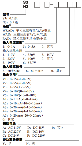
2. 型号及参数填写示例:
(1) N3-WRAD-3-555A4BY
0.5 级三相三线有功/无功功率/电流变送器(跨相法)
输入标称电流:5A;
输入标称电压:100V;
标称输入功率④(有功功率/无功功率):866W/866Var
输入信号频率:50±5Hz;
输出范围:4~20mA;对应 0~5A
4~12~20mA;分别对应 -866~0~866W /-866~0~866Var
辅助电源:AC220V。需要测量逆向功率。
(2) S3-WRAD-3T-555A4BY
0.2 级三相三线有功/无功功率变送器(移相法)
输入标称电流:5A;输入标称电压:100V;
标称输入功率④(有功功率/无功功率):866W/866Var
输入信号频率:50±5Hz;
输出范围:4~20mA;对应 0~5A
4~12~20mA;分别对应 -866~0~866W /-866~0~866Var
辅助电源:AC220V。需要测量逆向功率。
注:
①.系统:有T 标注,用移相法测量;无T标注,用跨相法测量。
②组合变送器中电流的测量为单独的,用户可以根据其系统要,任意接入A、B、C 相中的任一相电流。
③输出范围()内的值,为正、逆向功率输出时所指定值。对于无功功率测量:当输出负向值时,表示系统的容性阻抗最大;当输出正向值时,表示系统的感性阻抗最大。
④对系统功率的标定见前有功功率注释:②项。
⑤若用户需要其他特殊标定,请在合同中注明参数值。

