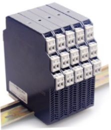

IP Series U/I SIGNAL ISOLATED TRANSMITTER
Quick Overview
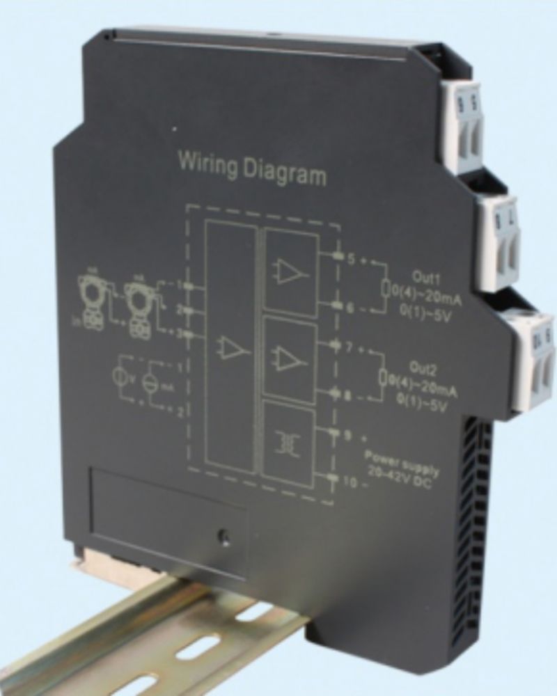
1.1DC24V or AC220V power supply, provide isolated power distribution for on-site transmitters, and realize the conversion of voltage, current, mV and other signals. 1.2 Input terminal interface current source, two-wire system, three-wire system transmitter universal;


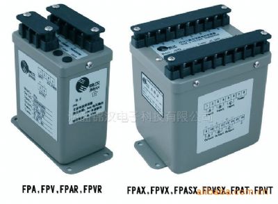
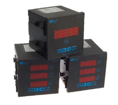
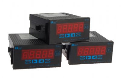
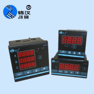
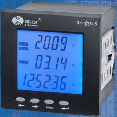
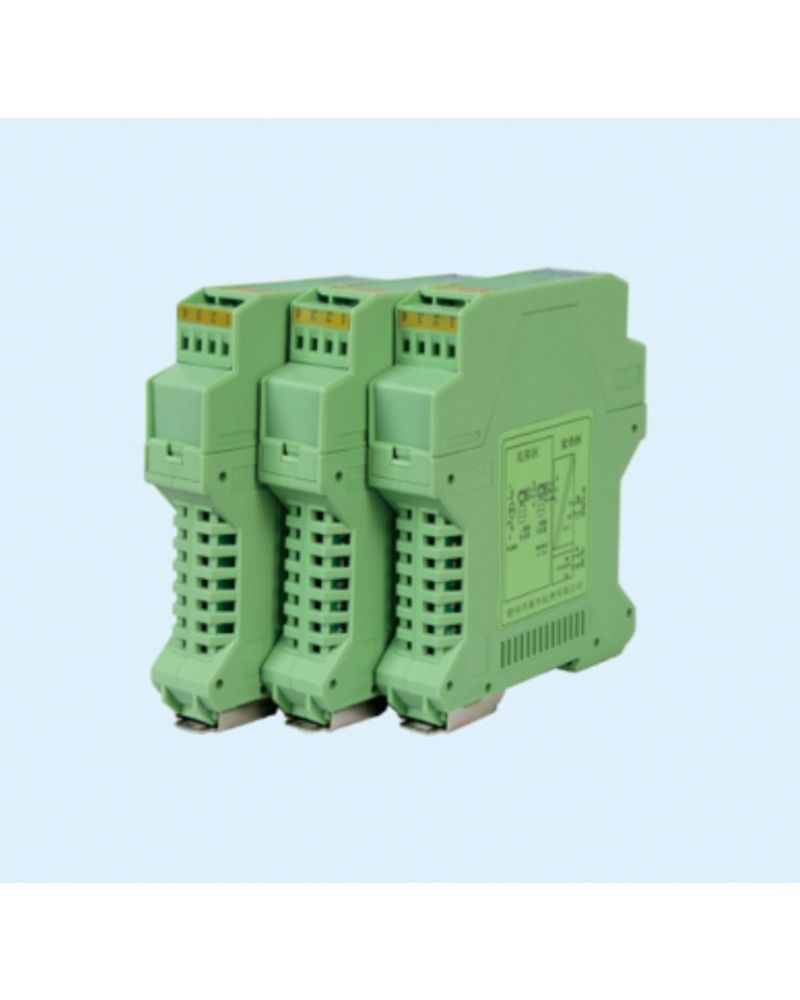
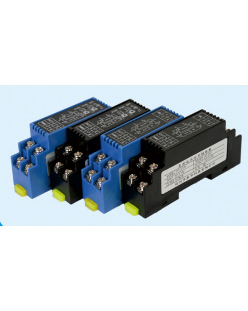
Related Products


1. Functions:
1.1DC24V or AC220V power supply, provide isolated power distribution for on-site transmitters, and realize the conversion of voltage, current, mV and other signals.
1.2 Input terminal interface current source, two-wire system, three-wire system transmitter universal;
1.3 The internal use of efficient magnetoelectric isolation technology, the input, output, power supply is isolated from each other, with high precision, high linearity, low temperature drift and other characteristics.
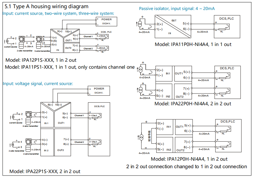
1.4 IP series passive isolators receive dc current or dc voltage signals from the field, and output 4-20ma current signals separately after interference suppression. 2 - wire circuit power supply, no external power supply
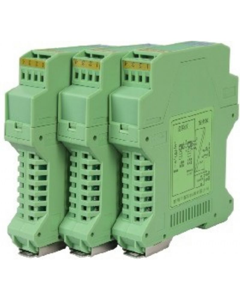
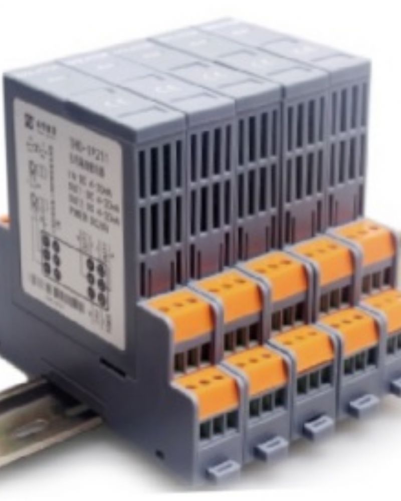
Features: DIN rail independent installation; Input, output, power three port high reliability isolation.
2. SPECIFICATION
2.1 Input impedance: Current input: ≤100Ω; voltage input: ≥300KΩ
2.2 output load resistance: RL ≤ 500Ω (when the output is a current signal)
RL ≥ 1KΩ (when the output is a voltage signal)
2.3 parameters
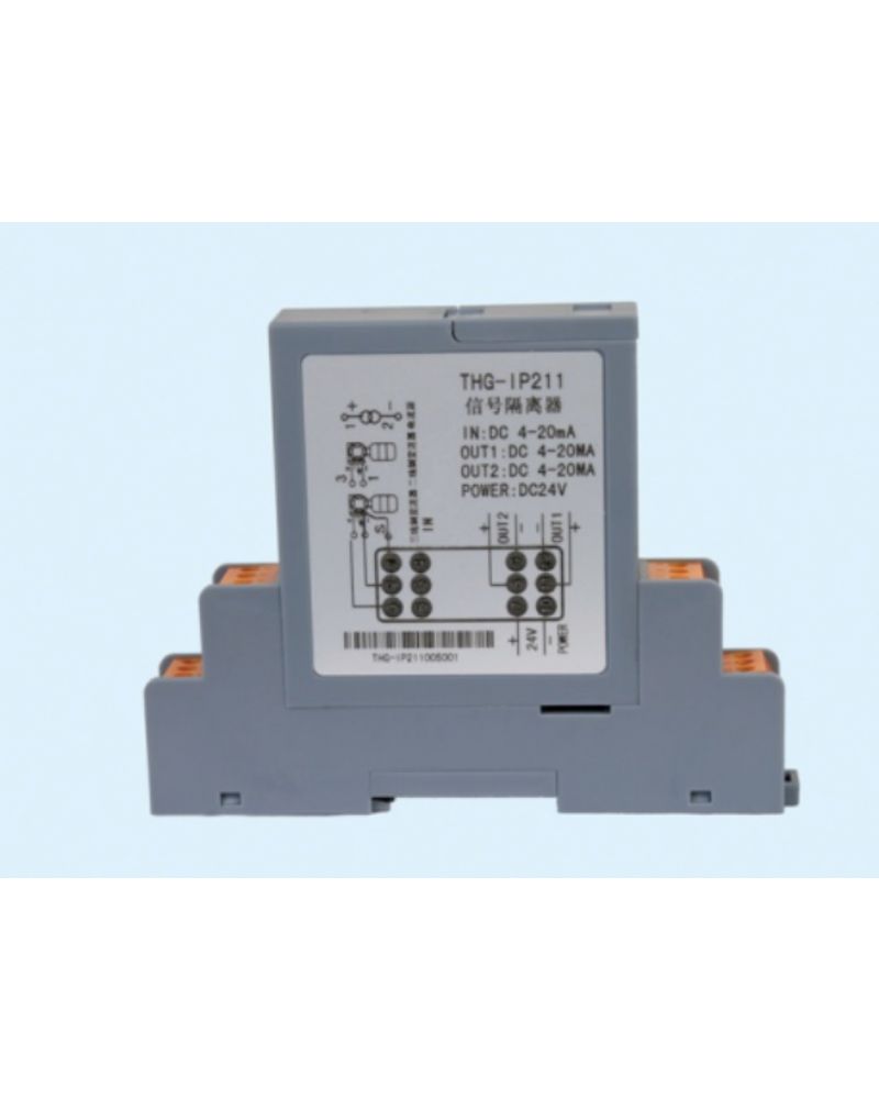
Power supply:DC24V, ±10%
Current consumption: ≤30mA (one input and one output, 24V power supply, 20mA output)
≤50mA (one input and two output, 24V power supply, 20mA output)
≤60mA (two in two out, 24V power supply, 20mA output)
Accuracy: 0.1% RO, 0.2%RO, 0.5%RO,
Temperature coefficient: 0.005% RO./°C (-20°C~+55°C)
Insulation strength: 1500V AC / 1min (between input, output and power)
Insulation resistance: ≥100MΩ (between input, output, and power)
2.4 Operating temperature : -20 ~ +55 ° C
2.5 Electromagnetic compatibility: in line with GB/T 18268 (IEC61326-1)
2.6 Applicable field devices: two-wire transmitter, current source, voltage signal output device.
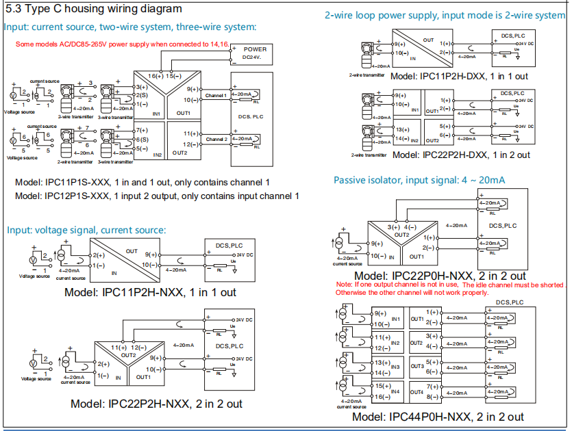
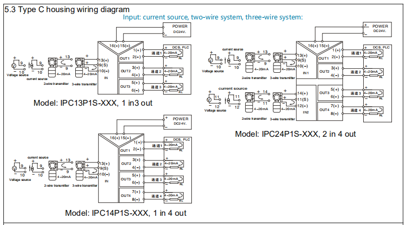
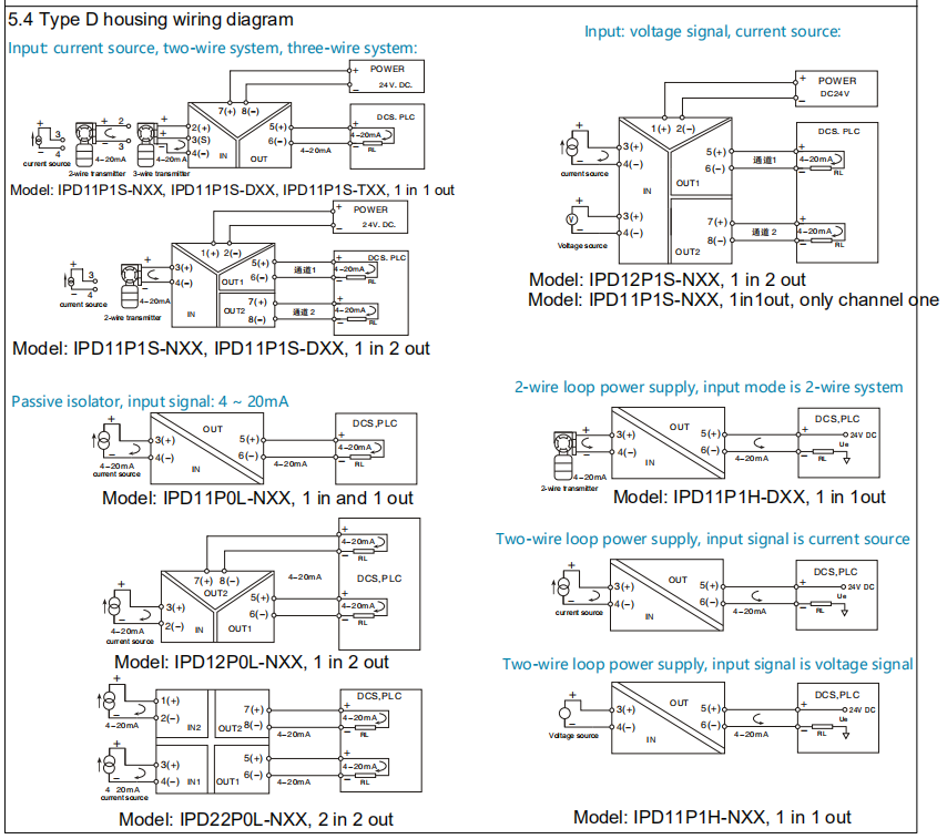
4.SCHEMATIC CIRCUITRY & CONNECTION DIAGRAM

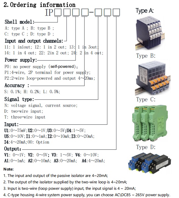
2.Ordering information:
4. Main model:
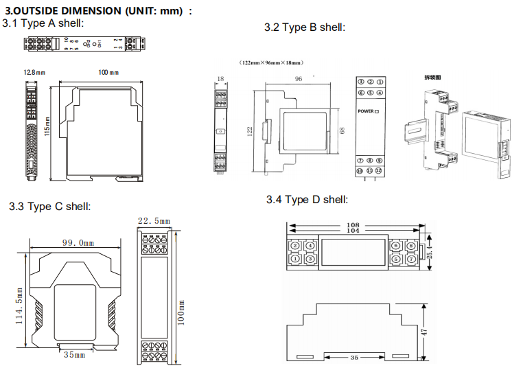
4.1 Type A shell models:
channels | self-powered P0 0.2%F.S | wire,P1 0.1%F.S |
1 in 1 out | IPA11P0H-NI4A4 | IPA11P1S-XXX |
1 in 2 out | IPA12P0H-NI4A4 | IPA12P1S-XXX |
2 in 2 out | IPA22P0SH-NI4A4 | IPA22P1S-XXX |
4.2 Type B shell models:
channels | self-powered P0 0.2%F.S | 4-wire P1 0.1%F.S | 2-wire P2 0.2%F.S |
1 in 1 out | IPB11P0H-NI4A4 | IPB11P1S-XXX | IPB11P2H-XXA4 |
1 in 2 out | IPB12P0H-NI4A4 | IPB12P1S-XXX | IPB12P2H-XXA4 |
2 in 2 out | IPB22P0H-NI4A4 | IPB22P1S-XXX | IPB22P2H-XXA4 |
4.3 Type C shell models:
channels | self-powered P0 0.2%F.S | 4-wire P1 0.1%F.S | 2-wire P2 0.2%F.S |
1 in 1 out | IPC11P1H-NI4A4 | IPC11P1S-XXX | IPC11P1H-XXA4 |
1 in 2 out | IPC12P1H-NI4A4 | IPC12P1S-XXX | IPC12P1H-XXA4 |
1 in 3 out | - | IPC13P1S-XXX | - |
2 in 2 out | IPC22P1H-NI4A4 | IPC22P1S-XXX | IPC22P1H-XXA4 |
4 in 4 out | IPC44P1H-NI4A4 | IPC24P1S-XXX | - |
4.4 Type D shell models:
channels | self-powered P0 0.2%F.S | 4-wire P1 0.1%F.S | 2-wire P2 0.2%F.S |
1 in 1 out | IPD11P1H-NI4A4 | IPD11P1S-XX | IPD11P2H-XXA4 |
1 in 2 out | IPD12P1H-NI4A4 | IPD12P1S-XX | - |
2 in 2 out | IPD22P1H-NI4A4 | IPD22P1S-XX | - |