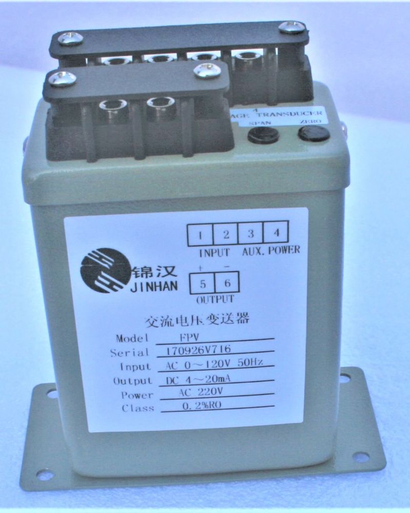
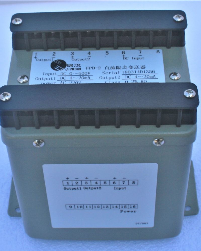
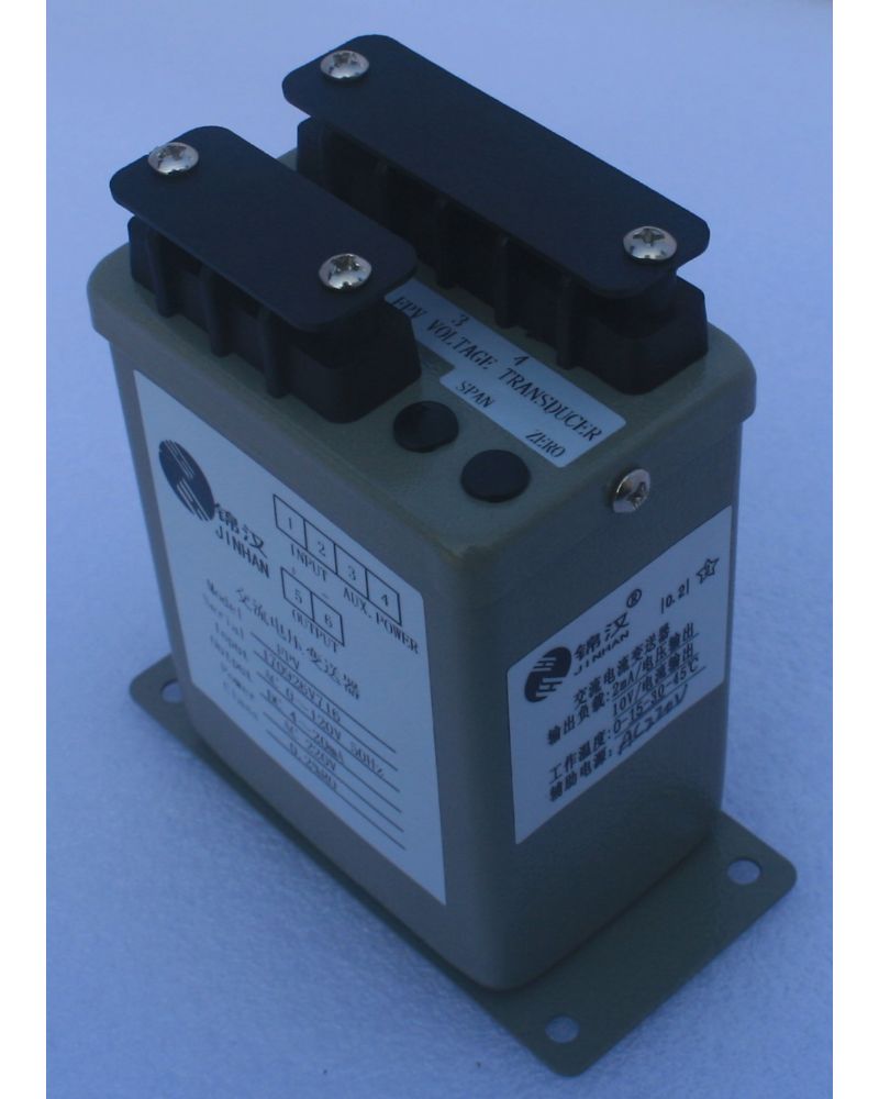
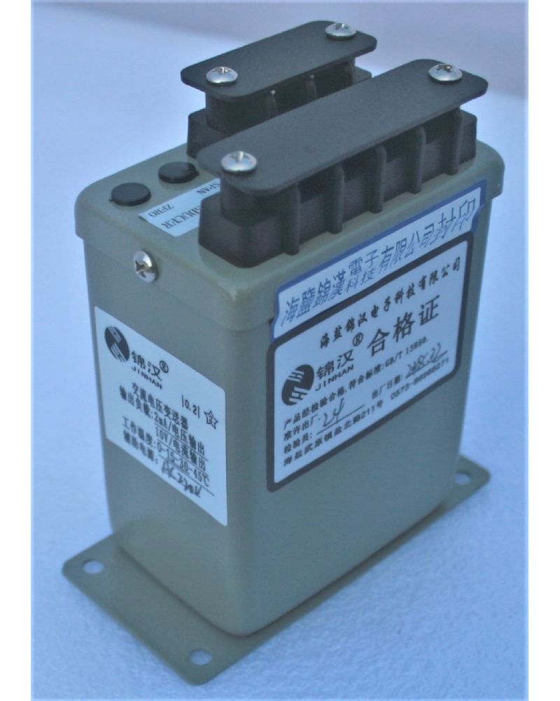
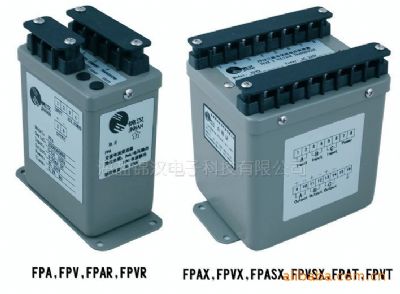
FPV&FPVX AC VOLTAGE TRANSDUCERS
Quick Overview
The AC current feeder is an instrument that converts the measured AC current into a DC current or voltage that is output in a linear ratio. With the corresponding indicator instrument or device, the measurement and control of current and voltage can be realized in the AC circuit of the power system.
Related Products
1.Introduction:
The AC current feeder is an transducer that converts the measured AC VOLTAGE into a DC current or voltage that is output in a linear ratio. With the corresponding indicator instrument or device, the measurement and control of current and voltage can be realized in the AC VOLTAGE of the power system.
The difference between FPVR and FPV is the true rms transformation, which does not affect the measurement accuracy with waveform distortion, so it is especially suitable for areas with severe waveform distortion.
Models and specifications:
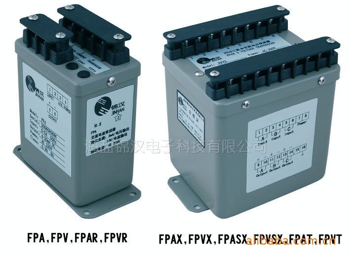
FPV: 1 unit of avg. to rms conversion
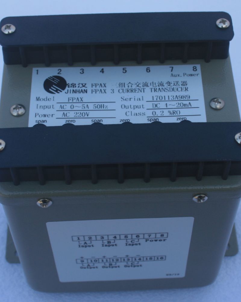
FPVX: 3 unit of avg. to rms conversion
FPVR: Ture rms conversion
FPVT:Dual output(avg. to rms conversion)
2.Specification
Accuracy ( 23±3℃) : |
| 0.2% RO:FPV, FPVX;0.4% RO:FPVR |
Maximum output load: |
| DC current mode : maximum 10V drop DC voltage mode : maximum 5mA drive |
Dielectric strength |
| AC 2KV 1 minute between terminals AC 2.6KV 1 minute / terminals to case |
Surge and impulse test |
| ANSI C37.90 / 1989,IEC 255-3 (1989) 4 KV 1.2 x 50 us |
Maximum input over |
| 1.5 x rated / continuous |
| 2 x rated / 10 seconds | |
Input burden |
| less 0.1 VA |
Response time & ripple |
| ≤400 ms for step change 0-99% ripple less 0.5% ro peak to peak |
Frequency |
| 45 ~ 400 Hz |
Stability |
| Temperature range ( 20 to 26°C ) long term stability / year Maximum 60 ppm / °C less 0.2% draft / year typically. |
Storage condition |
| Temperature range -25 to 70℃, RH 20 to 95% non condensed |
Operating condition |
| Temperature range -20 to 65°C, RH 0 to 99% non condensed |
Magnetic field effect |
| < 0.01% under 100 ampere turns at 1M center |
Power dissipation |
| Maximum 3.5 VA for FPV / FPVR; 8 VA for FPVX |
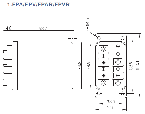
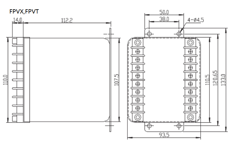
3.Dimensional Drawings

1.Order form:

Input & Output parameters
Vn: Voltage input | Vn rating range | V1 120V 0-150V | V2 240V 0-300V | V3 400V 0-450V | Vy Specified |
Fn: Input frequency | Fn rating range | F1 50Hz 45-55Hz | F2 60Hz 55-65Hz | F3 400Hz | Fy Specified |
Pn: Auxiliary power | Pn Rating | P1 AC110 V 120 V ± 15% | P2 AC220 V 240 V ± 15% | Ps Internal Power | Py Specified |
PDn ratingrange | PD1 DC110 V 120 V ± 15% | PD2 DC220 V 240 V ± 15% | PD3 DC24 V 24 V ± 20% | PDy Specified | |
On:Output | O1 0-1mA | O2 0-20mA | O3 4-20mA | O4 0-5mA | O5 0-10mA |
O7 0-1V | O8 0-5V | O9 0-10V | O10 2-10V | O11 1-5V |
Note:
1. FPV can be dual output;
2. "*" auxiliary power supply optional PD1: DC 110V, PD2: DC 220V.
When signing the order contract, the required model and specifications should be specified in detail. The selected model and specifications should be filled in with the code in the following format.
Example 1.
FPVT-V1-F1-P2-08/01
Dual output Voltage transducer
Input: 0-120V
Frequency: 50Hz
Auxiliary power supply: AC 220V
Output: 0-5V/0-1mA
Example2.
FPV-V1-F1-PD2-08 is calibrated to 0-150V
Voltage transducer
Input: 0-150V
Frequency: 50Hz
Auxiliary power supply: DC 220V
Output: 0-5V

