FPWH/FPKH WATT/WATTHOUR & VAR/VARHOUR TRANSDUCER
Quick Overview
Applied Standards & Rules: Measuring and conversion: IEC 688 / 1992 - 04; Dielectrical strength : IEC 688 2KVac / 1 min; Surge and Impulse test : ANSI C37.90 / 1989; IEC 255-3 (1989) 4KV 1.2 x 50 us;
Related Products
1.Introduction:
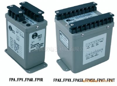
FPWH type active energy transmitter, FPKH type reactive energy transmitter is an instrument for measuring active and reactive energy, FPWWH type active power / active energy, FPKKH type reactive power / reactive power combined transmitter It is a dual-function instrument that can measure both active (or reactive) power and active (or reactive) power. It is an auxiliary instrument for energy metering, energy-saving automation and computer electricity billing.
FP series electric energy transmitter technical indicators fully comply with the requirements of JJG 596-89 "Electronic energy meter", the relative error is less than 0.5%, and has excellent temperature characteristics and long-term stability, coupled with electric energy display recording device, can be used In the grid dispatching system, it is also an ideal solid-state electric energy meter.
The transmitter is suitable for single-phase, three-phase (balanced load and unbalanced load) lines with frequency of 50Hz, 60Hz and special frequency. The electric energy is pulsed output with two types of optocoupler open collector or relay contact to adapt to different RTU and power recording device. The digital output corresponds to the active (or reactive) energy measured by the input. The output lead is four wires, and the bidirectional digital output outputs electrical energy in both positive and negative directions.
Main models:
2.Specification ![]()
Accuracy ( 23±3℃) : |
| 0.2% reading / PF ± 0.05% RO | ||
Maximum output load: |
| DC current mode : maximum 10V drop DC voltage mode : maximum 5mA drive | ||
Dielectric strength |
| AC 2KV 1 minute between terminals AC 2.6KV 1 minute / terminals to case | ||
Output of WH & VarH |
| Open collecter type, maximum 30V / 30mA | ||
Surge and impulse test |
| ANSI C37.90 / 1989,IEC 255-3 (1989) 4 KV 1.2 x 50 us | ||
Maximum input over |
| Current related input | Voltage related input | |
| 1A / 5A | 10A |
| |
| 4 x rated / continuous | 2 x rated / continuous | 1.5 x rated / continuous | |
| 10 x rated / 10 seconds | 25 x rated / 1 second | 2 x rated / 10 seconds | |
| 50 x rated / 1 second | 50 x rated / 0.5 second |
| |
| 80 x rated / 0.5 second |
|
| |
Input burden |
| Current less 0.2 VA; voltage less 0.1 VA | ||
Response time & ripple |
| ≤400 ms for step change 0-99% ripple less 0.5% ro peak to peak | ||
Frequency |
| 50 ± 2 Hz; 60 ± 2 Hz; 400 ± 5 Hz ( Watt only ) | ||
Waveform |
| Watt :- 2% 3rd, Var: - sinusoidal | ||
Stability |
| Temperature range ( 20 to 26℃), long term stability / year Maximum 70 ppm /℃, less 0.2% draft / year typically | ||
Storage condition |
| Temperature range -25 to 70℃, RH 20 to 95% non condensed | ||
Operating condition |
| Temperature range -20 to 65°C, RH 0 to 99% non condensed | ||
Magnetic field effect |
| < 0.01% under 100 ampere turns at 1M center | ||
Power dissipation |
| < 7 VA | ||
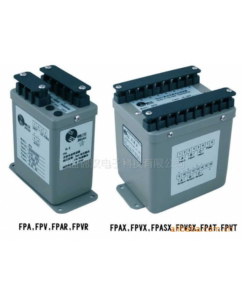
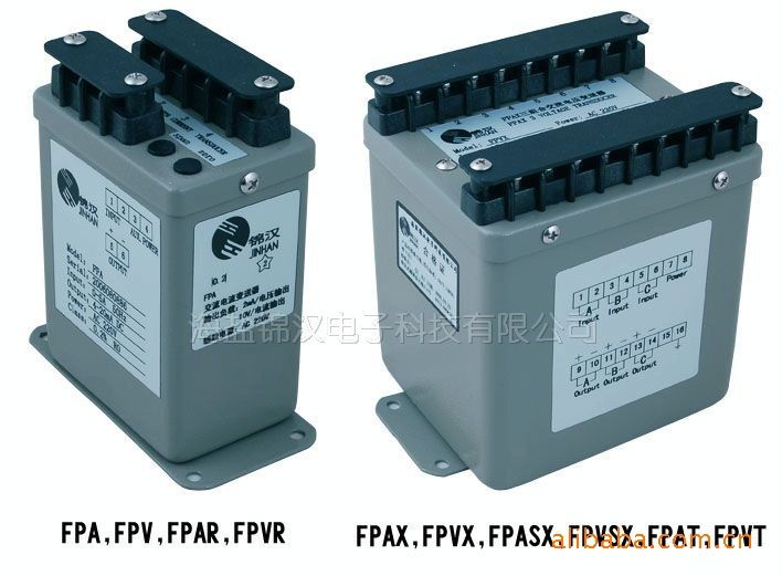
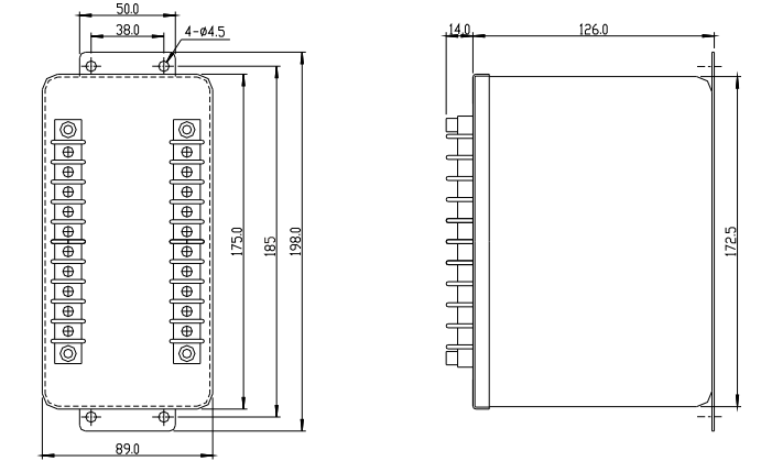
3.Outline dimension
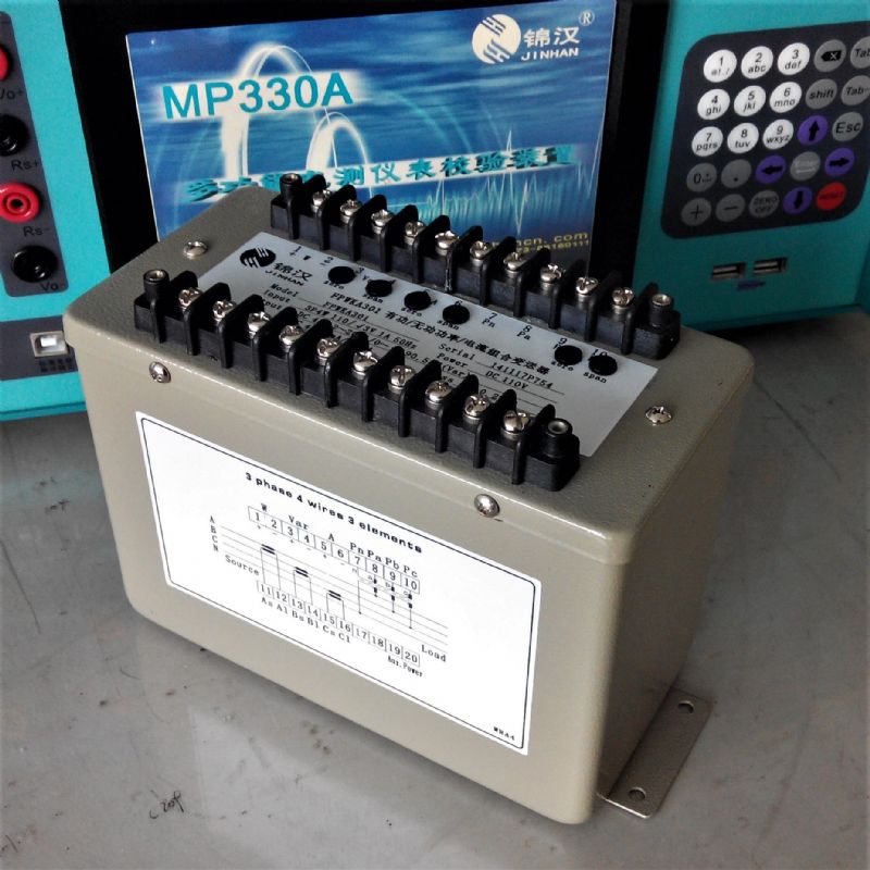
4.Terminal Connection:
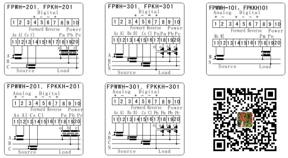
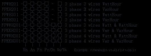
1.Order form:
Vn : Voltage input | Vn rating range | V1 100 | V2 220V 180-300V | V3 400V 320-450V | Vy Specified | On : Output | ||||
An : Current input | An rating range | A1 1A 0-1.2A | A2 5A 0-6A | A3 10A 0-12A | Ay Specified | O1 0-±1mA | O2 0-±20mA | O3 4-20mA | ||
Fn : Frequency input | Fn rating range | F1 50Hz 45-55Hz | F2 60Hz 55-65Hz | F3 400Hz | Fy Specified | O4 0-±5mA | O5 0-±10mA | O6 4-12-20mA | ||
Pn : Auxiliary power | Pn rating range | P1 AC110 V 120 V ± 15% | P2 AC220 V 240 V ± 15% | Ps Internal Power | Py Specified | O7 0-±1V | O8 0-±5V | O9 0-±10V | ||
PDn rating range | PD1 DC110V 120 V ± 15% | PD2 DC220V 240V± 15% | PD3 DC24 V 24 V ± 20% | PDy Specified | O10 2-10V | O11 1-5V | O12 1-3-5V | |||
Xn : Standard pulse output for uni-direction | Xn rating | X1 / X3 1 pulse / wh or varh | X2 / X4 10 pulse / wh or varh | X1, X2, Y1, Y2 : open collector type X3, X4, Y3, Y4 : reed relay type | ||||||
Yn : Optional pulse output for bi-direction | Yn rating | Y1 / Y3 1 pulse / wh or varh | Y2 / Y4 10 pulse / wh or varh | |||||||
Model | Application system | ||
Watt | Var | Elements - Connection | |
FPWWH201 | FPKKH201 | 2E | 3 phase 3 wires, unbalance |
FPWWH301 | FPKKH301 | 3E | 3 phase 4 wires, unbalance |
Note
1. Standard output calibration
bipolar 0 to ± 1mA for 0 to ± D Watts or Vars
4-12-20mA for -D to 0 to +D Watts or Vars
2. External power mode suitably for all output types
Internal power mode, only suitably for 0-1mA / 0-20mA / 0-1V / 0-5V / 0-10V output

