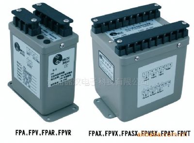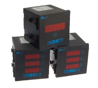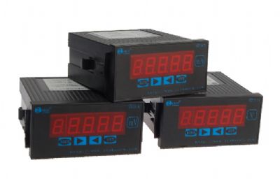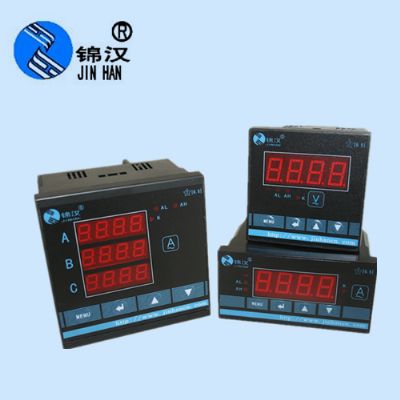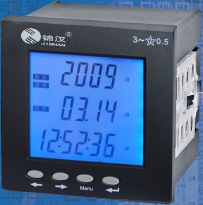


Related Products

1.FEATURES
◆Excellent long term stability (4 ~ 20mA, 500 W )
◆Precision measurement even for unbalance system
◆Precision measurement even for distorted wave
◆High impulse & surge protection (5KV)
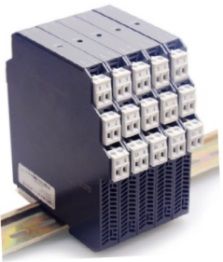
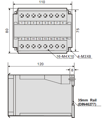
◆The case can be mounted on a 35mm rail which complies with DIN 46277.
2.DESCRIPTION
Model:
S3-RHD-1 1φ2W,± 0.2% RD ; N3-RHD-1 1φ2W,± 0.5% RD
S3-RHD-3 , ± 0.2% RD ; N3-RHD-3 3φ3W, ± 0.5% RD
S3-RHD-3A 3φ4W, ± 0.2% RD; N3-RHD-3 3φ3W, ± 0.5% RDFor kilovar-hour-measurement, we build in another Linear integrator Circuit. This circuit accepts signal from Vars portion and integrates with respect to time, to produce a pulse output via volt free contacts, result in pulse proportional to kilovar-hours.
For kilovar-hour-measurement, we build in another Linear integrator Circuit. This circuit accepts signal from Vars portion and integrates with respect to time, to produce a pulse output via volt free contacts, result in pulse proportional to kilovar-hours.
3.SPECIFICATION:
3.1 INPUT
Input Range
Max. Input Over Capability
Circuit
Amp.
Voltage
Basic Var
Single Phase
5 A
110V (120V)
± 0.5KVarH
Ampere:
3 x rated continuous
10 x rated 10 sec.
50 x rated 1 sec.
Voltage:
2 x rated continuous
220V (240V)
± 1KVarH
3-Phase 3-Wire
5 A
110V (120V)
± 1KVarH
220V (240V)
± 2KVarH
3-Phase 4-Wire
5 A
190V/110V (208/120V)
± 1.5KVarH
380V/220V (416/240V)
± 3KVarH
Input Range | Max. Input Over Capability | |||
Circuit | Amp. | Voltage | Basic Var | |
Single Phase | 5 A | 110V (120V) | ± 0.5KVarH | Ampere: 3 x rated continuous 10 x rated 10 sec. 50 x rated 1 sec.
Voltage: 2 x rated continuous |
220V (240V) | ± 1KVarH | |||
3-Phase 3-Wire |
5 A | 110V (120V) | ± 1KVarH | |
220V (240V) | ± 2KVarH | |||
3-Phase 4-Wire | 5 A | 190V/110V (208/120V) | ± 1.5KVarH | |
380V/220V (416/240V) | ± 3KVarH | |||
3.2 OUTPUT:
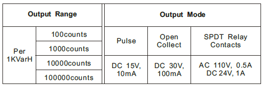
3.2 OUTPUT:
4. Specification:&, lt;, /p>
Aux. power supply | AC 110V ± 15%, 50/60HZ AC 220V ± 15%, 50/60HZ DC24V, 48V, 110V, ± 15% |
Power consumption | -2.5VA, ≤DC 3W |
Power effect | ≤0.1% RO |
Waveform effect | ≤0.2% RO. at distortion factor 30%( PCIR) |
Output load effect | ≤0.05% RO. |
Magnetic field strength | -0.2% RO., 400A/M |
Span adjustment range | 5%RO |
Zero adjustment range | 1%RO |
Operating temperature range | 0 ~ 60℃ |
Operating temperature range | 0 ~ 60℃ |
Storage temperature range | -10 ~ 70℃ |
Temperature coefficient | - 100PPM from 0 to 60℃ ≤ 60PPM, 25。C ± 10℃ |
Max. relative humidity | 95% |
Isolation | Input/output/power/case |
Insulation resistance | 100M W, DC 500V |
Dielectric withstand voltage | Between input/output/power/case (IEC 414, 688,ANSI, C37) AC 2.6KV, 60HZ, 1 min. |
Impulse withstand test | 5KV, 1.2 X 50μS (IEC 255-4, ANSI C37 90a) Common mode & differential mod |
Performance | Designed to comply with IEC688 |
Safety requirements | IEC 414, BS5458 |
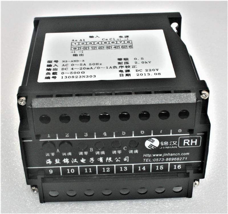
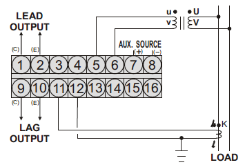
5、Trminal Connection:
◆S3-RHD-1, N3-RHD-1 (1φ2W)
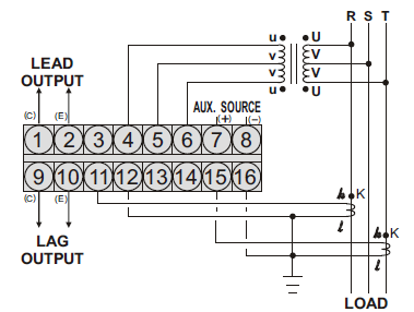
◆S3-RHD-3, N3-RHD-3 (3φ3W)
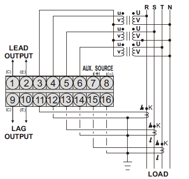
◆S3-RHD-3A, N3-RHD-3A (3φ4W)
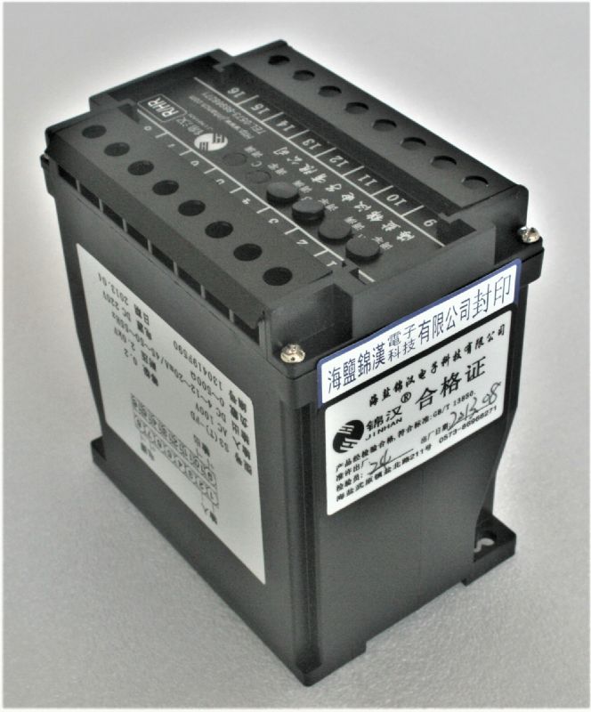
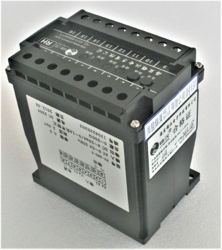
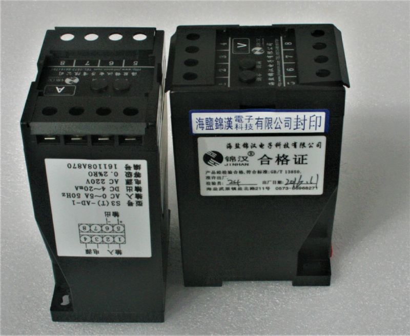
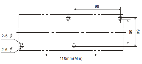
6.THE OUTSIDE DIMENSION (UNIT:mm)
1.Model:
S3-RHD-1 :1φ2W reactive power transducer, accuracy: 0.2% RO
S3-RHD-3 :3φ3W reactive power transducer, accuracy: 0.2% RO
S3-RHD-3A :3φ4W reactive power transducer, accuracy: 0.2% RO
N3-RHD-1 :1φ2W reactive energy transducer, accuracy: 0.5% RO
N3-RHD-3 :3φ3W reactive power transducer, accuracy: 0.5% RO
N3-RHD-3A :3φ4W reactive power transducer, accuracy: 0.5% RO
2.Order form:
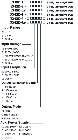
3. Example of model and parameter filling:
(1) S3-RHD-3-5553CBY
0.2%RO, 3φ3W reactive energy transducer (cross-phase )
Input nominal current: 5A; input nominal voltage: 100V;
Nominal input power 5: 866Var;
Input signal frequency: 50±5Hz;
Output range (power constant): 10000 pulses / kVarh
Output type: no voltage pure contact (optocoupler open collector output);
Auxiliary power supply: AC220V.
Need to measure reverse power (capacitive load)
(2) N3-RHD-3T-5552CBY
0.5%RO,3φ3W reactive power transducer
Input nominal current: 5A; input nominal voltage: 100V;
Nominal input power 5: 866Var;
Input signal frequency: 50±5Hz;
Output range (power constant): 1000 pulses / kVarh
Output type: no voltage pure contact (optocoupler open collector output);
Auxiliary power supply: AC220V.
Need to measure reverse power (capacitive load).
Note:
1 system: T mark, measured by phase shift method; no T mark is measured by cross-phase method.
2 The output range (pulse number) of reactive energy transmitter is calibrated according to 1kVarh. For reactive energy measurement, when the output is negative, it means that the capacitive impedance of the system is the largest; when the positive value is output, it means that the inductive impedance of the system is the largest.
3 system select the appropriate output type see active energy notes: 2 items.
4 When measuring the forward and negative energy of the system, the power signal is output separately.
5 calibration of system power see active power note: 2 items.
6 If the user needs other special calibration, please indicate the parameter value in the contract.