WATT/WATTHOUR & VAR/VARHOUR TRANSDUCER
Quick Overview
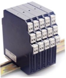
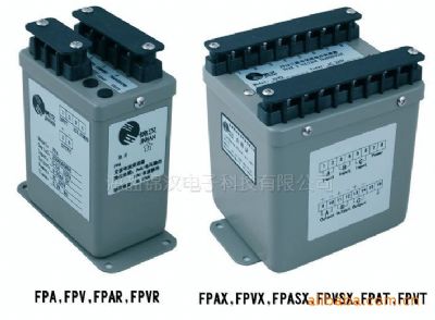
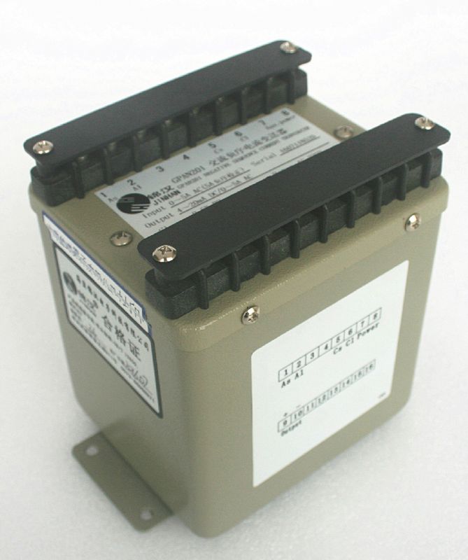
he GPWWH are electronic transducers converting active power and energy in single or three phase balanced or unbalanced systems to simultaneously produce an analogue DC output for instantaneous power signal and a digital pulse output for cumulative energy signal.


Related Products
GPWH/GPKH active energy / reactive energy transducer
GPWWH active power / active power combined transducer
GPKKH reactive power / reactive energy combined transducer
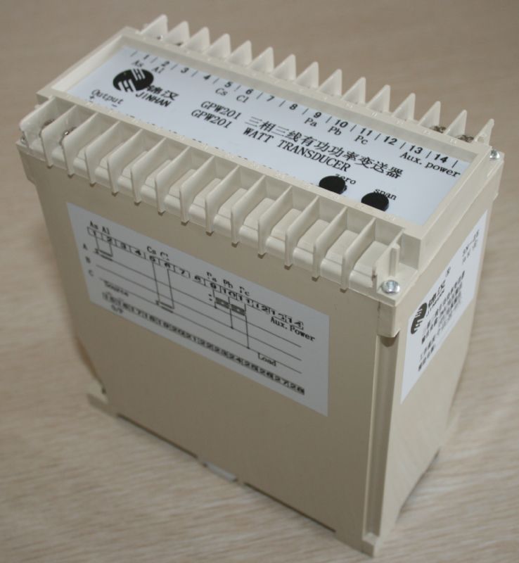
1.Introduction:
The GPWWH are electronic transducers converting active power and energy in single or three phase balanced or unbalanced systems to simultaneously produce an analogue DC output for instantaneous power signal and a digital pulse output for cumulative energy signal.
The GPKKH are electronic transducers converting reactive power and energy in three phase balanced or unbalanced systems to simultaneously produce an analogue DC output for instantaneous power signal and a digital pulse output for cumulative energy signal.
Applied Standards & Rules
Measuring and conversion: IEC 688 / 1992 - 04
Dielectrical strength :IEC 688 2KVac / 1 min.
Surge and Impulse test :ANSI C37.90 / 1989
IEC 255-3 (1989) 4KV 1.2 x 50 us
Reference Standard :GB/T 13850-1998(IEC688-1992)
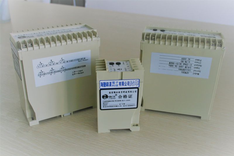
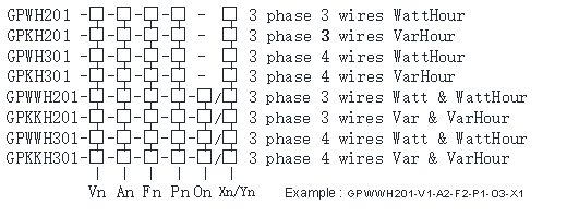
2.Models and specifications:
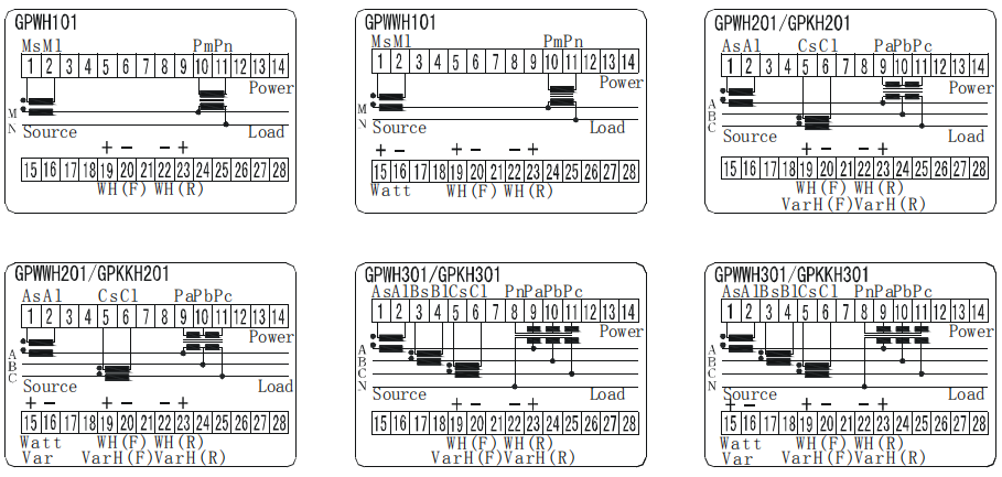
GPWH201: 3 phase 3 wires WattHour
GPKH201: 3 phase 3 wires VarHour
GPWH301: 3 phase 4 wires WattHour
GPKH301: 3 phase 4 wires VarHour
GPWWH201:3 phase 3 wires Watt & WattHour
GPKKH201: 3 phase 3 wires Var & VarHour
GPWWH301: 3 phase 4 wires Watt & WattHour
GPKKH301: 3 phase 4 wires Var & VarHour
* Active Energy / Reactive Energy Accuracy: 1.0% Relative Error
3.Specification
Reference Standard: | GB/T 13850-1998(IEC688-1992) |
Accuracy: | 0.5%RO according to IEC 688-1,At(23±5℃) |
Long term stability: | ≤±0.5%/year,No accumulation error |
Temperature influence: | <100ppm/℃ |
Response Time: | <400ms |
Output Ripple: | <1.0% (peak-peak value) |
Input burden: | Current less 0.2VA;voltage less 0.1VA |
Frequency: | Nominal frequency ±10% |
Maximum output load: | Current output Max10V pressure drop Voltage output rated 2mA MAX 5mA output |
Auxiliary power: | Power dissipation <7 VA |
Auxiliary load effect: | <0. 2 % |
Allow excessive input: | Current 2 rate continuous 20 rate1 secs voltage max 2 rate continuous |
Dielectric strength: | Input/output/power/betwem the crust 2KV,AC 1 min IEC866 |
Impact test: | ANSI C37.90a/1973,IEC 255-4,(5kV 1.2/50us Pulsed Voltage) |
Calibration amplitude: | Full scale least<±3%,zero least<±1% |
Magnetic field effect: | 0.4KA/m magnetic field strength change<0.05% |
Operating condition: | Temperature -10~55℃relative humidity ≤95% RH non condensing |
Storage condition: | Temperature-40~70℃ relative humidity ≤95% RH non condensing |
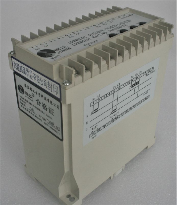
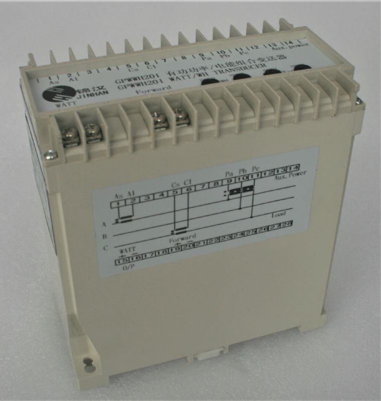
3.Trminal Connection:
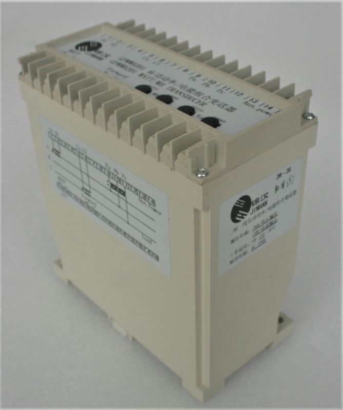
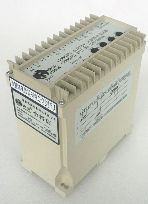
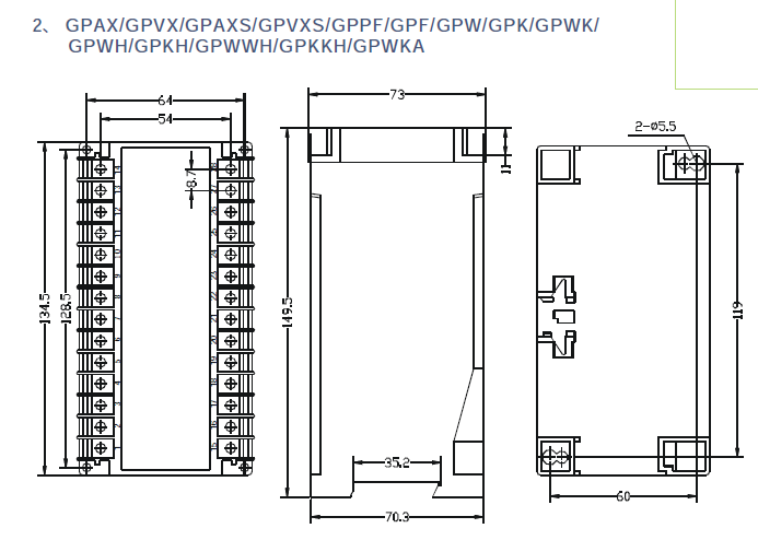
4.Dimensional Drawings:
1.Order form:
2. Input & Output parameters:
Vn : Voltage input | Vn rating range | V1 100 | V2 220V 180-300V | V3 400V 320-450V | Vy Specified | On : Output | ||||
An : Current input | An rating range | A1 1A 0-1.2A | A2 5A 0-6A | A3 10A 0-12A | Ay Specified | O1 0-±1mA | O2 0-±20mA | O3 4-20mA | ||
Fn : Frequency input | Fn rating range | F1 50Hz 45-55Hz | F2 60Hz 55-65Hz | F3 400Hz | Fy Specified | O4 0-±5mA | O5 0-±10mA | O6 4-12-20mA | ||
Pn : Auxiliary power | Pn rating range | P1 AC110 V 120 V ± 15% | P2 AC220 V 240 V ± 15% | Ps Internal Power | Py Specified | O7 0-±1V | O8 0-±5V | O9 0-±10V | ||
PDn rating range | PD1 DC110V 120 V ± 15% | PD2 DC220V 240V± 15% | PD3 DC24 V 24 V ± 20% | PDy Specified | O10 2-10V | O11 1-5V | O12 1-3-5V | |||
Xn : Standard pulse output for uni-direction | Xn rating | X1 / X3 1 pulse / wh or varh | X2 / X4 10 pulse / wh or varh | X1, X2, Y1, Y2 : open collector type X3, X4, Y3, Y4 : reed relay type | ||||||
Yn : Optional pulse output for bi-direction | Yn rating | Y1 / Y3 1 pulse / wh or varh | Y2 / Y4 10 pulse / wh or varh | |||||||
Note
1. Standard output calibration
bipolar 0 to ± 1mA for 0 to ± D Watts or Vars
4-12-20mA for -D to 0 to +D Watts or Vars
2. External power mode suitably for all output types
Internal power mode, only suitably for 0-1mA / 0-20mA / 0-1V / 0-5V / 0-10V output