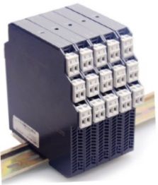

GPF FREQUENCY TRANSDUCER
Quick Overview
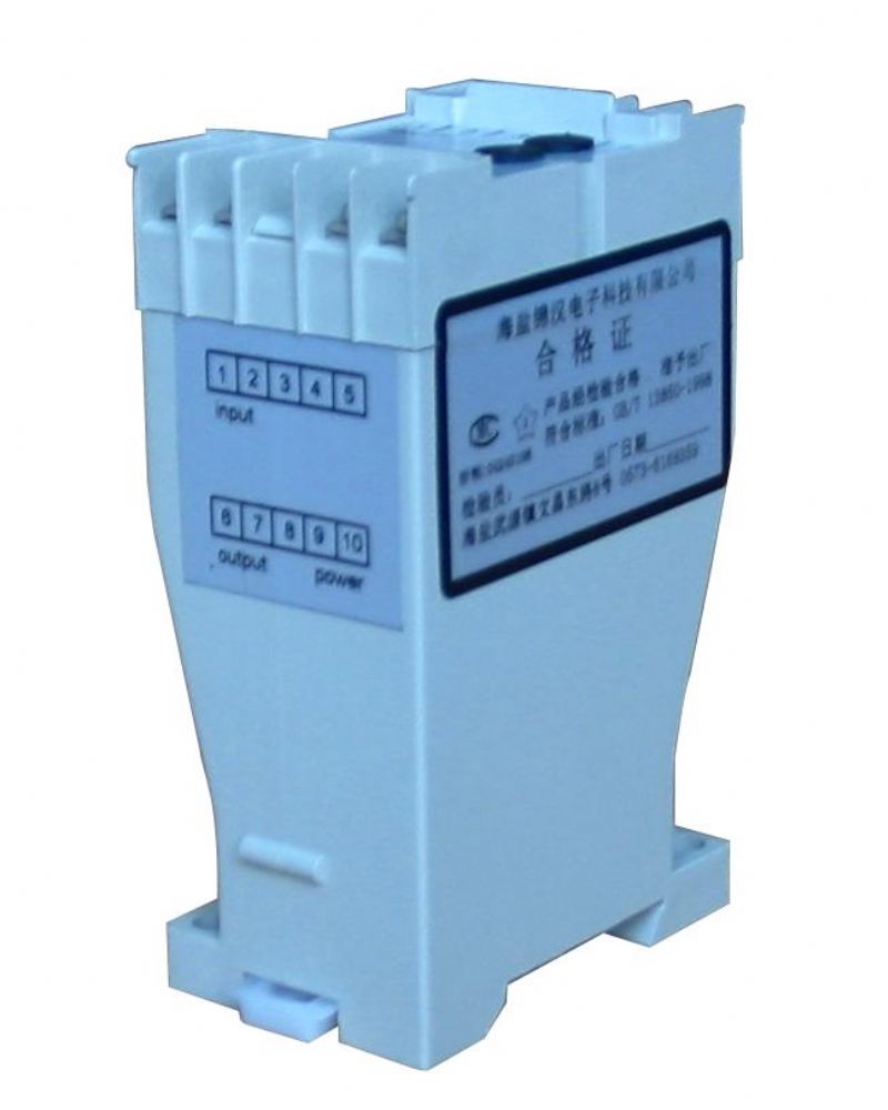
The GPF frequency transducer converts AC voltage to a linear DC output signal proportional to the frequency of the input. Employing a crystal based oscillator conversion principle, the measured frequency band is accurately represented by proportional linear DC voltage or current output.


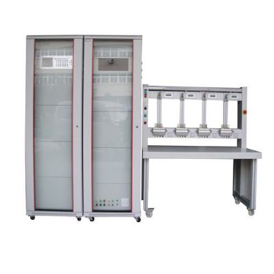
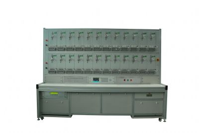
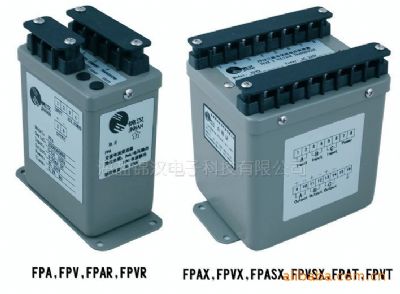
Related Products
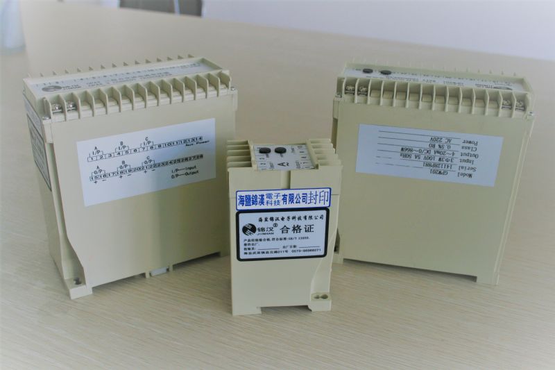
GPF FREQUENCY TRANSDUCER
1.Introduction:
The GPF frequency transducer converts AC voltage to a linear DC output signal proportional to the frequency of the input. Employing a crystal based oscillator conversion principle, the measured frequency band is accurately represented by proportional linear DC voltage or current output.
Applied Standards & Rules
Measuring and conversion: IEC 688 / 1992 - 04
Dielectrical strength: IEC 688 2KVac / 1 min.
Surge and Impulse test : ANSI C37.90 / 1989, IEC 255-3 (1989) 4KV 1.2 x 50 us
Models and specifications:
GPF - frequency transducer: accuracy: 0.5%RO
2.Specification
Reference Standard: | GB/T 13850-1998(IEC688-1992) |
Accuracy: | 0.5%RO according to IEC 688-1,At(23±5℃) |
Long term stability: | ≤±0.5%/year,No accumulation error |
Temperature influence: | <100ppm/℃ |
Response Time: | <400ms |
Output Ripple: | <1.0% (peak-peak value) |
Input burden: | Current less 0.2VA;voltage less 0.1VA |
Frequency: | Nominal frequency ±10% |
Maximum output load: | Current output Max10V pressure drop Voltage output rated 2mA MAX 5mA output |
Auxiliary power: | < 3VA (for GPA & GPAR);< 8VA (for GPAX); |
Auxiliary load effect: | <0. 2 % |
Allow excessive input: | Current 2 rate continuous 20 rate 1 secs voltage max 2 rate continuous |
Dielectric strength: | Input/output/power/betwem the crust 2KV,AC 1 min IEC866 |
Impact test: | ANSI C37.90a/1973,IEC 255-4,(5kV 1.2/50us Pulsed Voltage) |
Calibration amplitude: | Full scale least<±3%,zero least<±1% |
Magnetic field effect: | 0.4KA/m magnetic field strength change<0.05% |
Operating condition: | Temperature -10~55℃relative humidity ≤95% RH non condensing |
Storage condition: | Temperature-40~70℃ relative humidity ≤95% RH non condensing |
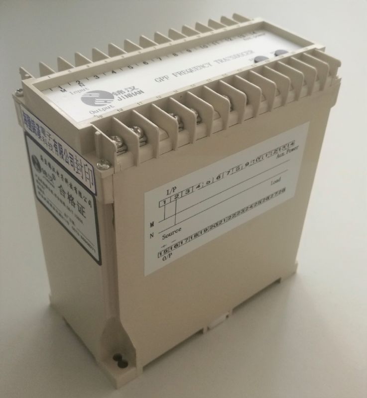
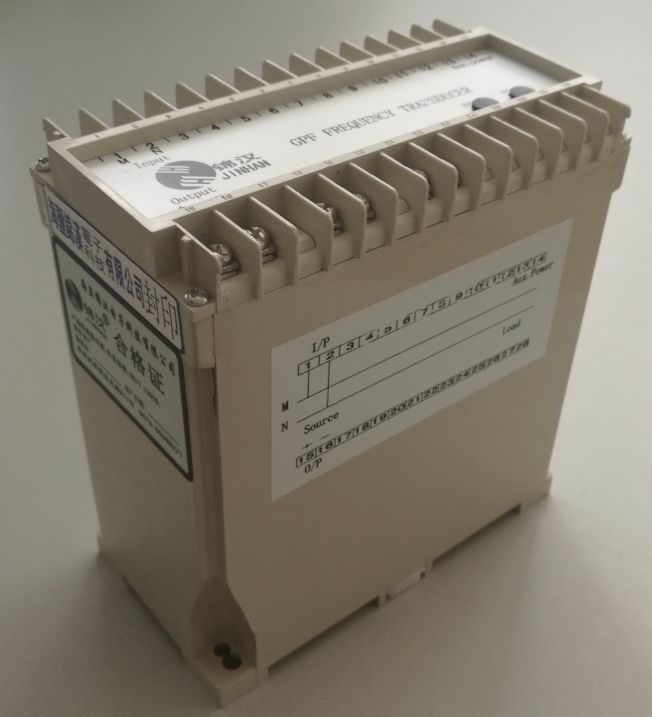
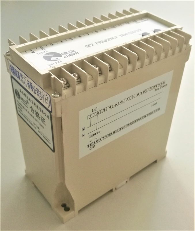
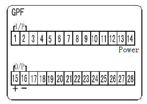
3.Trminal Connection::
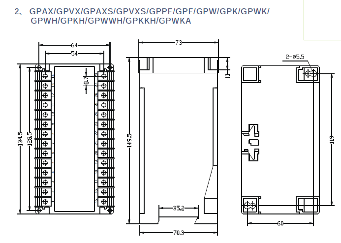
4.Dimensional Drawings:
1.Order form:

Input & Output parameters
Fn : Frequency input | Fn range | F1 50 Hz | F2 60 Hz | F3 400 Hz |
Specified | On : Output | ||
Pn : Auxiliary power | Pn rating range | P1 AC110 V 120 V ± 15% | P2 AC220 V 240 V ± 15% | Ps Internal Power | Py Specified | O1 0-1mA | O2 0-20mA | O3 4-20mA |
PDn rating range | PD1 DC110 V 120 V ± 15% | PD2 DC220 V 240V ± 15% | PD3 DC24 V 24 V ± 20% | PDy Specified | O4 0-5mA | O5 0-10mA |
| |
| Bn range | B1 ±0.5 Hz | B2 ±1 Hz | B3 ±2 Hz | B4 ±5 Hz | O7 0-1V | O8 0-5V | O9 0-10V |
B5 ±10 Hz |
|
|
| O10 2-10V | O11 1-5V | Oy Specified | ||
Py : DC24 / 48 / 125 V ±15% or other range under specified Voltage input range : 30 - 600 Vac
Note
1. External power mode suitably for all output types
Internal power mode, only suitably for 0-1mA / 0-20mA / 0-1V / 0-5V / 0-10V output
2. Sample filling of model and parameters:
Example 1: GPF - F1 - P2 - O8 / B2
Frequency transducer
Input: 49 ~ 51Hz
Auxiliary power supply: AC 220V
Output: 0 ~ 5V/49 ~ 51Hz
Example 2: gpf-f1-p2-o13 /B3 output -5v ~ 0V ~ 5V
Frequency transducer
Input: 48 ~ 52Hz
Auxiliary power supply: AC 220V
Output: -5v ~ 0V ~ 5V / 48 ~ 50 ~ 52Hz